Riiven Threads
MEMS Gyroscope and Accelerometer
The Sesame Seed That Knows Up
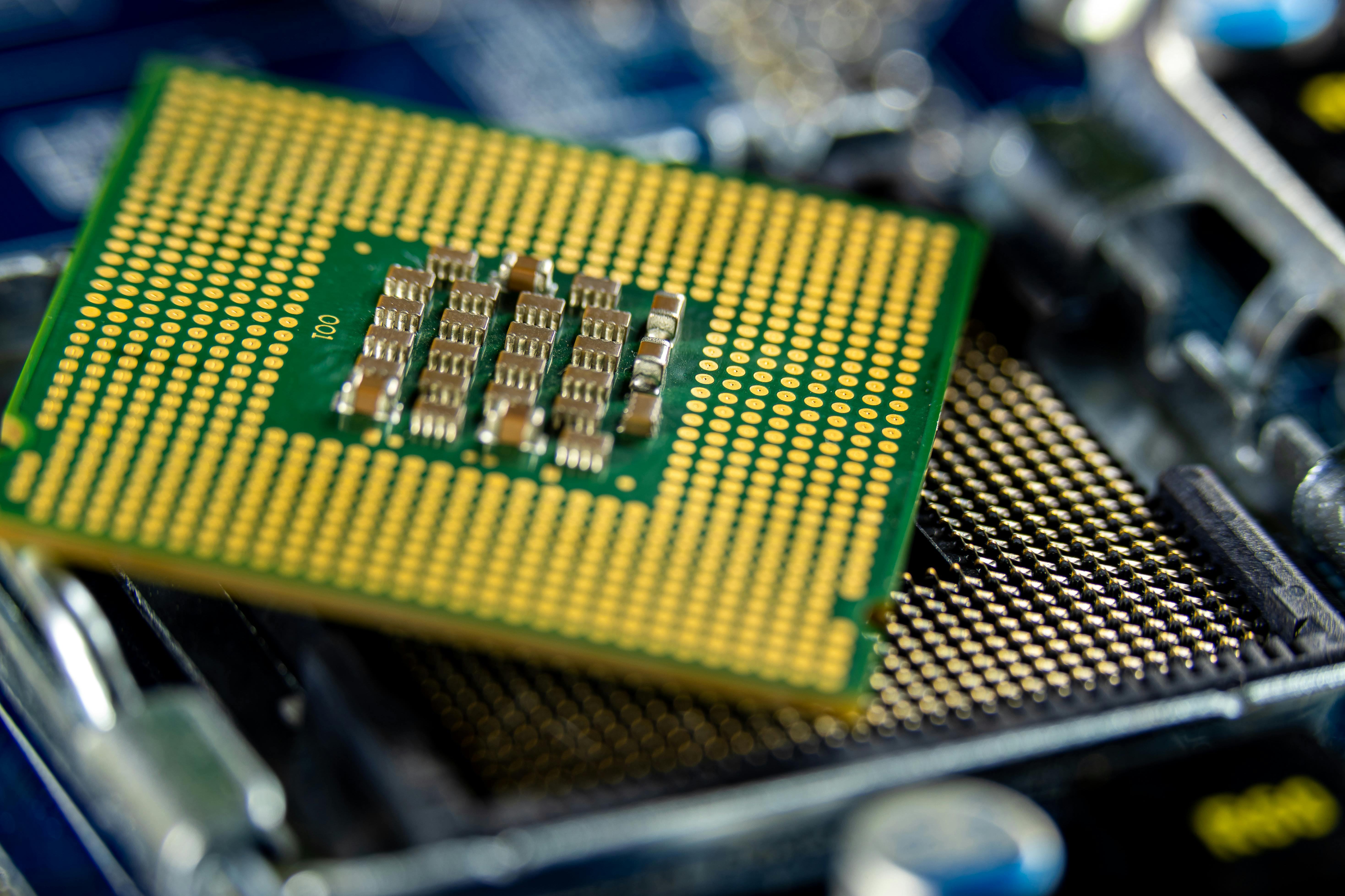
You tilted your phone today and the screen rotated. Inside, two chips the size of sesame seeds picked up the change: one for gravity, one for rotation. Each is a silicon proof mass on springs, deflecting by nanometers when your hand moves it, with the bend read by a circuit that listens for capacitance changes as small as one attofarad on a femtofarad baseline. The mechanics is from 1835. The vacuum sealing is a 1969 process. The silicon etching that lets you build a moving part on a chip is from 1982. By 2010, Apple paid about three dollars to put both into iPhone 4. The phone calls them sensors. They are silicon ears, listening for motion smaller than a silicon atom.
- 1attofarad
- The capacitance shift a MEMS sensor must resolve, set off by motion smaller than an atom's width.
- 100x Q-factor drop
- Mechanical quality falls more than 100-fold without vacuum sealing, making the gyroscope unreadable.
- 188GPa
- Silicon's stiffness, near steel, with zero measurable fatigue over a lifetime of cycling.
- 100x cost increase
- Without batch wafer fabrication, each MEMS sensor would cost roughly 100 times more per unit.
When the fields matured
Each field had to produce a specific result before MEMS Gyroscope and Accelerometer could exist as you know it. The timeline below shows when each one arrived.
Pull any thread, and the same story unravels.
In the order the story needs them, not the order they happened. Each card carries the year its field matured.
Keystone
The finger structure that made in-plane motion possible
A MEMS gyroscope's proof mass has to vibrate sideways across the chip, not up and down. Three Berkeley engineers in 1989 invented the comb drive that makes that motion possible at micron scale.
Early micromachined resonators all vibrated perpendicular to the wafer surface, like tiny diving boards. That motion is hard to drive electrostatically without wasting most of the force on the substrate. William Tang, Tu-Cuong Nguyen, and Roger Howe at Berkeley in 1989 demonstrated an interdigitated finger structure, a lateral comb drive, that vibrates parallel to the chip surface with force proportional to voltage squared and independent of in-plane position. Every modern MEMS gyroscope drives its proof mass with a descendant of that comb.
Without this field
Without lateral comb-drive transduction, MEMS resonators must operate in out-of-plane modes that are mechanically coupled to the substrate and electrostatically inefficient. Vibratory gyroscope drive amplitudes drop by orders of magnitude, and stable closed-loop oscillation becomes nearly impossible to maintain at smartphone power budgets.
Without the lateral comb-drive transduction demonstrated by Tang, Nguyen, and Howe in 1989, in-plane resonant operation up to 80 kHz on micromachined polysilicon is unavailable, forcing MEMS resonators back into out-of-plane modes that couple to the substrate and cannot sustain stable vibratory gyroscope drive amplitudes at consumer power budgets
How we know
Tang, Nguyen, and Howe's 1989 Sensors and Actuators paper Laterally Driven Polysilicon Resonant Microstructures introduced the interdigitated comb-finger geometry on a 2 micron polysilicon film and demonstrated resonant frequencies from 18 kHz to 80 kHz with Q factors between 20 and 130 in air. The comb's geometry decouples the electrostatic force from the rest gap, giving force that is independent of in-plane displacement and proportional to voltage squared. That linearity is what makes closed-loop gyroscope drive electronics feasible. Every commercial vibratory MEMS gyroscope, from the InvenSense IDG-300 onward, uses lateral comb drives or close variants for both the drive and the sense axes.
Source: Laterally Driven Polysilicon Resonant Microstructures (1989) · tier1
But a comb that swings in-plane is useless without a physical law to interpret what the swing means under rotation.
Coriolis in 1835, writing the equation gyros still obey
Your phone's gyroscope reads a force first written down in 1835. Gaspard-Gustave Coriolis was working on industrial waterwheels at the time, 175 years before iPhone 4 shipped with a MEMS gyro.
Gaspard-Gustave Coriolis was working on the efficiency of industrial rotating machinery when he published, in 1835, the equations describing the apparent force on a mass moving inside a rotating frame. That force is now called the Coriolis force. A MEMS gyroscope works by vibrating a proof mass back and forth at tens of kilohertz, then measuring the perpendicular bend induced when the chip rotates. Without Coriolis's equations, that bend has no physical interpretation and the gyroscope cannot exist.
Without this field
Without the Coriolis principle applied to vibrating MEMS structures, the only practical way to build a gyroscope is to keep a heavy disc spinning, which requires bearings, motors, lubrication, and continuous milliwatts to watts of power. Smartphones, drones, and vehicle stability systems would have no compact rate sensor and would fall back to bulky mechanical or expensive optical gyros.
How we know
Coriolis's 1835 memoir Sur les équations du mouvement relatif des systèmes de corps appeared in Journal de l'École Polytechnique Cahier XXIV, pages 142-154. He derived the inertial force on a mass m moving with velocity v in a frame rotating at angular velocity omega: F equals minus two m times the cross product of omega and v. MEMS vibratory gyroscopes drive a proof mass to oscillate along one axis at frequencies typically between 10 and 30 kilohertz, then sense the orthogonal displacement caused by the Coriolis force when the device rotates. The measured displacement is proportional to the input rotation rate, which is the gyroscope output. No rotating part is needed. The math is 191 years old; the silicon is from this century.
Source: Sur les équations du mouvement relatif des systèmes de corps (1835) · tier1
The physics was settled in 1835, but the material capable of surviving billions of vibration cycles took another 147 years to be recognized.
Petersen's paper that recast silicon as a spring
Silicon was supposed to carry electrons, not weight. Kurt Petersen at IBM proved otherwise in a 1982 review paper that turned the chip industry into a mechanical-parts industry.
Before 1982, silicon was strictly the chip industry's transistor material. Kurt Petersen's review paper in Proceedings of the IEEE compiled, with measurements, evidence that silicon's Young's modulus is comparable to steel, its tensile strength higher than stainless, and it shows no measurable fatigue under cyclic loading at room temperature. That single paper convinced funders and engineers they could etch beams, springs, diaphragms, and proof masses directly into silicon wafers. Every MEMS device that came after, including the accelerometer in your phone, is built on that conclusion.
Without this field
Without Petersen's 1982 recognition that silicon is a structural material, MEMS device structures would have used electroplated nickel or polymers, both of which fatigue or creep under repeated load. Long-term sensor stability collapses within months, and integrating mechanical structures with on-chip electronics on a single wafer becomes effectively impossible.
Without recognition of single-crystal silicon as a structural material, MEMS designers would substitute electroplated nickel or polymers with Young's modulus typically under 200 GPa and measurable fatigue cycles, losing the up to 188 GPa near-steel stiffness and the zero-fatigue lifetime that silicon proof masses depend on
How we know
Petersen's 1982 Proceedings of the IEEE article compiled mechanical data on silicon scattered across two decades of research and presented it as engineering design guidance. Young's modulus of 130 to 188 GPa depending on crystal orientation, fracture strength of cleaved silicon up to about 7 GPa, zero measurable fatigue under cyclic loading at room temperature, anisotropic etch behavior in KOH and EDP. The paper has been cited more than 2,800 times on IEEE Xplore and remains one of the most-cited single references in MEMS. It is why MEMS device design uses silicon as both structure and substrate, instead of plating metals onto a separate carrier.
Source: Silicon as a Mechanical Material (1982) · tier1
Knowing silicon could flex without failing answered what to build from; keeping that motion from bleeding into surrounding air was a separate problem entirely.
A few hundred volts fusing glass to silicon since 1969
A MEMS gyroscope dies in open air because gas damping kills its resonance. Wallis and Pomerantz at PR Mallory found the seal that saves it in 1969: fuse glass to silicon with a few hundred volts.
A vibrating MEMS structure in open air loses energy to gas damping so fast that its mechanical Q factor falls to single digits, which makes the gyroscope unreadable. Sealing the resonator in a vacuum cavity raises Q above 10,000, but the seal must survive thermal cycling, soldering, and decades of slow leakage. George Wallis and Daniel Pomerantz at PR Mallory found in 1969 that you can fuse glass directly to silicon by applying a few hundred volts. Anodic bonding, glass-frit bonding, and eutectic bonding are the family of seals used on wafer-level MEMS gyro packages today.
Without this field
Without wafer-level vacuum sealing, the mechanical quality factor of a MEMS vibratory gyroscope drops from above 10,000 in vacuum to below 100 in air. Below a Q of 100, the Coriolis signal is swamped by drive feedthrough and the device cannot produce a useful rotation-rate output at consumer power budgets.
Without anodic-bonded wafer-level vacuum packaging tracing back to Wallis and Pomerantz in 1969, the mechanical quality factor of a MEMS vibratory gyroscope falls from above 10,000 in vacuum to under 100 in atmospheric pressure, a 100-fold or worse loss that makes the device incapable of resolving the Coriolis signal at consumer power budgets
How we know
Wallis and Pomerantz's 1969 Journal of Applied Physics paper Field Assisted Glass-Metal Sealing described a process that fuses borosilicate glass to a metal or silicon surface at 300 to 500 degrees Celsius by applying 300 to 1000 volts across the joint, well below the softening point of the glass. Mobile sodium ions in the glass migrate away from the interface, leaving an oxygen-rich depletion layer that bonds chemically to silicon. Modern MEMS foundries use the same physics for wafer-level capping: a glass or silicon cap is bonded onto the device wafer in vacuum, sealing the resonator at around 1 millitorr. Quality factors above 2 million have been reported on quad-mass MEMS gyroscopes using ultrahigh-vacuum capping, against a Q under 100 for the same device at atmospheric pressure.
Source: Field Assisted Glass-Metal Sealing (1969) · tier2
The resonator could now vibrate in vacuum without losing energy to air, but the deflection it produced was still too small for any circuit of that era to read.
Reading a signal smaller than a silicon atom's width
At its noise floor, a MEMS proof mass moves a distance smaller than a silicon atom and changes capacitance by attofarads. Boser and Howe at Berkeley figured out how to read that signal in 1996.
At minimum signal, the proof mass inside a MEMS accelerometer or gyroscope moves a distance smaller than a silicon atom. The capacitance change between the mass and a nearby electrode is on the order of an attofarad against a baseline of a few femtofarads. Bernhard Boser and Roger Howe's 1996 IEEE Journal of Solid-State Circuits paper laid out a CMOS switched-capacitor interface and a noise budget showing that signal is reachable inside a coin-cell power budget. Every commercial MEMS inertial sensor uses a descendant of that architecture.
Without this field
Without low-noise CMOS readout circuits matched to MEMS capacitance, the sub-attofarad signal coming out of the proof mass is buried in amplifier noise. Bandwidth, resolution, and power all collapse: the sensor either draws too much current to fit a phone battery, or it cannot detect the tilts and rotations the application needs.
Without CMOS sigma-delta interface circuits matched to MEMS capacitance as analyzed by Boser and Howe in 1996, the attofarad-scale capacitance change between proof mass and electrode cannot be resolved within smartphone power budgets, making consumer-grade MEMS inertial sensors infeasible
How we know
Boser and Howe's 1996 paper Surface Micromachined Accelerometers analyzed the complete noise budget of capacitive position-sense interface circuits for MEMS, covering both Brownian thermal noise from the proof mass and electronic noise from the front-end amplifier. They laid out switched-capacitor charge-amplifier interfaces and showed that, with the right CMOS design, sub-attofarad capacitance changes corresponding to micro-g acceleration are reachable. Descendant circuits in the years since have pushed this to about 0.1 attofarad per root hertz and noise floors near 25 micro-g per root hertz. The paper is the design template every modern MEMS readout ASIC still follows.
Source: Surface Micromachined Accelerometers (1996) · tier1
The circuit could finally hear the sensor, but a device that costs hundreds of dollars stays out of a phone's bill of materials regardless of how well it works.
Airbags drove the price to three dollars by 2010
A precision accelerometer used to cost hundreds of dollars. Analog Devices sold the first single-chip MEMS one in 1991 for five dollars, then the IC cost curve did the rest.
Analog Devices' ADXL50, the first commercial single-chip MEMS accelerometer, sold in 1991 for about five dollars in volume to airbag system makers. That price was only possible because Analog Devices co-fabricated the MEMS structure with its readout electronics on a single die, inheriting the cost curve of the semiconductor industry. By 2010, iPhone 4's 3-axis MEMS accelerometer and 3-axis MEMS gyroscope carried a combined bill of materials of about $3.25 per iSuppli teardowns. Without batch wafer processing, unit cost would stay an order of magnitude higher.
Without this field
Without batch wafer fabrication economics, every MEMS device must be machined or assembled individually like a watch part. Per-unit cost stays above 100 dollars, which restricts use to aerospace and industrial markets, and a consumer phone integrating six axes of MEMS inertial sensing becomes unbuildable at any volume price.
Without batch wafer-scale fabrication inherited from the silicon IC industry, MEMS inertial sensors would cost 100 fold or more per unit, on the order of 100 dollars each instead of a few dollars in volume, removing them from consumer device bills of materials and confining MEMS to industrial and aerospace markets
How we know
Analog Devices announced the ADXL50 in 1991 as the world's first single-chip MEMS accelerometer, with mechanical and electronic structures co-fabricated on a die roughly 5 mm by 5 mm. Volume pricing to automotive customers was around five dollars per chip, against prior airbag accelerometers built from spring-mass ball-in-tube or piezoelectric assemblies that cost 15 to 50 dollars each. Per-die cost in MEMS scales like a digital IC: wafer cost divided by die count. By the time Apple shipped iPhone 4 in June 2010, iSuppli teardowns put the ST L3G4200D 3-axis gyroscope alone at about $2.60, with the LIS331DLH accelerometer adding under a dollar, for a combined six-axis bill of materials around three dollars. The economics is the IC economics, transplanted whole.
Source: MEMS, Engineering and Technology History Wiki (2015) · tier2
Watch
A visual companion to the fields above.
Takeaway
The MEMS gyro and accelerometer is the rare invention that gets stranger the closer you look. A sesame seed. A silicon spring. A pair of electrodes. But the reason your phone responds to tilt and rotation instantly, anywhere, for free, is that six separate fields each had to mature first, then land on the same square millimeter of silicon by the early 2000s. Petersen at IBM in 1982, proving silicon is also a mechanical material. Coriolis in 1835, writing down the inertia trick that vibrating masses feel under rotation. Tang, Nguyen, and Howe at Berkeley in 1989, making comb drives that swing parallel to a chip. Wallis and Pomerantz in 1969, sealing glass to silicon under vacuum with a few hundred volts. Boser and Howe in 1996, building CMOS readouts low-noise enough to resolve sub-attofarad capacitance changes. Analog Devices in 1991, selling the whole package for five dollars because airbags needed it. Your phone's sense of which way is up is what those six answers produce once they share a single square millimeter of silicon.
References
- Laterally Driven Polysilicon Resonant Microstructures (1989) tier1
Tang W.C., Nguyen T.-C.H., Howe R.T., Sensors and Actuators Vol 20 pp 25-32, 1989. First demonstration of lateral comb-drive transduction now used in essentially all commercial vibratory MEMS gyroscopes.
- Sur les équations du mouvement relatif des systèmes de corps (1835) tier1
Coriolis G.G., Journal de l'École Polytechnique Cahier XXIV Tome XV, pp 142-154, 1835. The original derivation of the Coriolis force, scanned facsimile on Internet Archive.
- Silicon as a Mechanical Material (1982) tier1
Petersen K.E., Proceedings of the IEEE Vol 70 No 5 pp 420-457, May 1982. The foundational paper that established silicon's mechanical properties for MEMS engineering, cited over 2,800 times.
- Field Assisted Glass-Metal Sealing (1969) tier2
Wallis G. and Pomerantz D.I., Journal of Applied Physics Vol 40 No 10 pp 3946-3949, 1969. Foundational paper on anodic bonding, the technique used for wafer-level vacuum packaging of MEMS resonators.
- Surface Micromachined Accelerometers (1996) tier1
Boser B.E. and Howe R.T., IEEE Journal of Solid-State Circuits Vol 31 No 3 pp 366-375, March 1996. Definitive noise analysis of capacitive interface circuits for MEMS inertial sensors.
- MEMS, Engineering and Technology History Wiki (2015) tier2
Engineering and Technology History Wiki (IEEE-affiliated history archive), MEMS entry. Documents the 1991 Analog Devices ADXL50 as the first commercial single-chip MEMS accelerometer and the batch wafer economics that brought MEMS sensors into automotive airbag and later consumer markets.